Cable tray supports and busway support fabrication
Data Center Metalworks fabricates build to print cable tray supports, trapeze hangers, bracing frames and strut style brackets. We work from the buyer approved support layout and part drawings. Send the load, connection, material and finish requirements for review by our team in Irving, Texas and Pompano Beach, Florida.
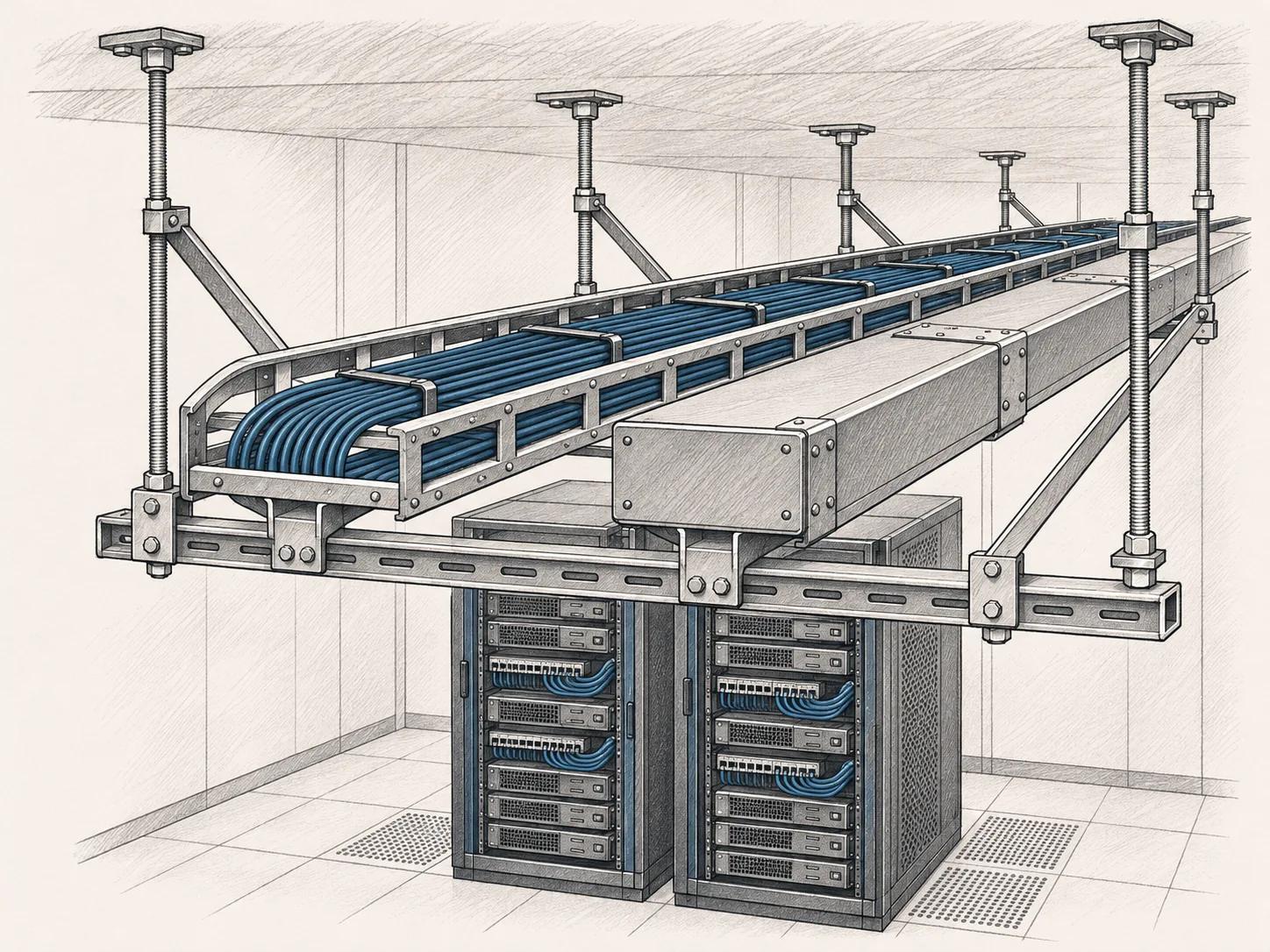
A support package starts with a layout
Cable tray and busway supports connect the equipment layout to the building structure. The package can include cross members, plates, brackets and braces. A clear drawing tells the fabricator where each part fits and which connection it serves. A general corridor photo cannot replace the required dimensions and loads.
Send the support schedule with the part details. Give each support type a mark that matches the plan. Identify repeated assemblies and the special parts at corners, offsets and changes in height. State whether the quantity is a count of individual pieces or complete kits. That distinction helps avoid a quote that includes only part of the intended installation.
Trapeze hangers and tray supports
A trapeze support uses a cross member with the specified suspension or attachment arrangement. The design must establish the span, load and connection details. Show the hole locations, rod or bolt requirements and any limits on field adjustment. If the design calls for slots, define their size and orientation rather than leaving them to the shop.
Cable tray supports also need a clear interface with the tray. Include the tray maker and series where the detail relies on specific hardware. A bracket that fits 1 tray profile may not fit another. List the clips, hold downs, isolators and fasteners in the kit, and mark whether they are supplied by the buyer or included in the quote.
Busway supports and bracing frames
Busway support geometry follows the equipment layout and the approved connection details. Provide the manufacturer interface drawing when it controls the support. Include the equipment weight and the loads used by the responsible engineer. The fabrication team should not infer a safe support spacing from the outside size of the busway.
Where the project calls for bracing, send the engineered arrangement and its acceptance requirements. Identify the structure to which the brace connects. Include connection plates, weld symbols and any special hardware. A bracing frame is not automatically a seismic qualified assembly. Required calculations, anchors and approvals need a defined owner before the fabrication scope is accepted.
Strut style brackets and custom plates
Custom brackets can solve a specific fit problem when the approved design calls for them. The drawing should show the bend direction, material grade, thickness and hole pattern. Mark the face that locates the supported item. Show clearance for the tool used to tighten each connection. A bracket that can be assembled on a bench may be hard to reach overhead.
When a custom part connects to a branded support system, identify the exact mating components. The term strut style describes a shape or function; it does not establish compatibility with every channel system. Keep any permitted alternatives in writing. If an equivalent is proposed, it should be reviewed against the actual connection and load requirements.
Kits that follow the installation sequence
Define the kit by a bill of materials and an assembly mark. Include a packing list with the part revision and quantity required for each kit. Tell us whether hardware should be loose, bagged by assembly or installed. Ask for any labeling and delivery sequence in the quote so it can be included in the plan.
The finish needs its own specification. State the exposure, coating system and any areas that must remain bare. Ask us about powder coat; its process route is pending confirmation. If coated purchased hardware is included, specify its grade and finish as well. A kit should not contain an assumed fastener just because its thread appears to fit.
Fabrication built around the support detail
A support kit combines parts that must reach the right location together. Match the plates, brackets and fasteners to the approved installation detail. Show the material, hole pattern and finish for each fabricated item. The quote should identify the complete kit contents, how the pieces are marked and which inspection records are required before release.
Our laser cutting, forming and welding processes support review of the specified plates and brackets. Irving has an Amada 3.5 kW CO2 laser, an Accupress brake and MIG welding. Florida has a Mazak laser, CNC press brakes and robotic welding. Rich reviews the actual dimensions, material and joints before assigning the route. The engineer approved connection detail remains the basis of the part.
Start with a drawing package
Use the RFQ form to send your support kit requirement. Include the company, contact name, email, plant location, quantity and target date. Attach a PDF, DXF or STEP file up to 25 MB. A dimensioned PDF should identify the current revision and the features that control fit. Add the material grade, thickness, finish and any inspection or packing notes.
Show the required kit quantity, contents and destination. If kits are released by area or installation stage, include that sequence with the dates. Kevin Leonard handles accounts, while Rich Fitzgerald reviews production and sourcing. Name the technical authority for connection or load questions. The accepted quote must define the support parts and release plan without changing the engineer approved design.
BUYER QUESTIONS
Details worth asking about.
Start with the specification. Confirm the details in your written quote.
Do you supply complete cable tray systems?
This page covers fabricated supports and related kits made to buyer drawings. Branded cable tray and busway equipment must be identified separately by manufacturer and series. The accepted quote defines any purchased hardware included with the metal parts.
Who determines the support load and spacing?
The project designer or other responsible engineer defines those requirements. Send the approved layout, loading and connection details for fabrication review. A shop quote does not replace the engineered support design.
Can Irving make brackets and plates?
Irving has an Amada 3.5 kW CO2 laser, an Accupress brake and MIG welding. Send the size, material and drawing so Rich can confirm the process and plant allocation. Published capacity hours and tolerance limits are still pending.
Can you ship supports as labeled kits?
Include the kit list, assembly marks, labels and packing sequence in the RFQ. Those requirements can then be priced and agreed with the fabrication scope. Kit completeness is checked against the accepted bill of materials, not an informal parts description.
NEXT STEP / YOUR DRAWING
A part number.
A print. A starting point.
Send the drawing, quantity and target date. Kevin handles your account. Rich reviews production and sourcing.
Request a quote